
Cutting the Cord: From USB to Direct CAN Bus
Driving I2RT YAM arms over direct CAN on a Jetson AGX Orin
The arm just stopped
Out of the box, I2RT's YAM arms communicate with the computer through a small USB-C-to-CAN adapter. The adapter ships pre-flashed with candleLight, an open-source firmware that makes it appear to Linux as a standard CAN port. With a single arm on a desk, this works well. Our deployments, however, involve more connections: two follower arms, two leaders, and several USB cameras. In that setup, it did not hold up. Picture a robot arm halfway through a motion when it simply stops, and then falls. The arm stops responding, the gravity compensation holding it up switches off, and the robot becomes a liability and a safety hazard.
After a round of debugging, we found that the USB-C link was not as reliable as it looked. Adapters dropped off the bus and came back, and the connection maintained by the software never recovered. Over time, the USB-C port on the adapter itself wore out and began to experience dropouts of its own. USB-C is a well-established standard, but it was never designed for a cable that gets tugged, unplugged and replugged over and over. Latching connectors such as JST-GH or Molex Micro-Fit, which click into place, would suit this job far better, but there's no easy way to swap one in for USB. That didn't sit right with us. Every patch we added made the system more complicated, and none of them removed the root cause: USB sitting in the motor path.
It's just CAN. How hard can it be?
As engineers, one fact kept coming back to us: the arm does not speak USB at all. Its motors communicate over CAN (Controller Area Network), one of the most widely used and thoroughly documented protocols in engineering (ISO 11898), and the same bus that runs inside most cars. The adapter is only a translator. If we could speak CAN ourselves, we would not need it. Decoding it shouldn't be that hard, right?
So where do we start reverse engineering? I2RT's documentation covered installing and running the library, but not the frames on the wire, so we went to the code.
Our first stop was the simulator. A simulation built to match the real robot should send the same CAN signals, we reasoned, so the commands would be sitting right there. It turned out to be pure physics, MuJoCo all the way down, with no CAN anywhere. So we followed the code one folder over, to the driver that talks to the real arm. And there were the frames ready to be decoded.
The CAN frames: a quick rundown
Readers interested mainly in the hardware can skip ahead to the next section.
- A frame is an ID plus up to 8 bytes. The YAM bus runs at 1 Mbit/s, with an 11-bit ID.
- One motor per frame. The host commands motor 1 on ID
0x001, which replies on0x011(ID + 0x10), then moves on to motor 2. A full round of seven motors takes about 1.8 ms. - Four special commands. Each is seven
0xFFbytes, then one last byte that picks the command:
| Last byte | Command | What it does |
|---|---|---|
FC |
Enable | Powers the motor up so it follows commands |
FD |
Disable | Switches the motor off; the joint goes limp |
FB |
Clear error | Resets a fault so the motor can be enabled again |
FE |
Save zero | Never send. Permanently resets the motor's zero to wherever it happens to be |
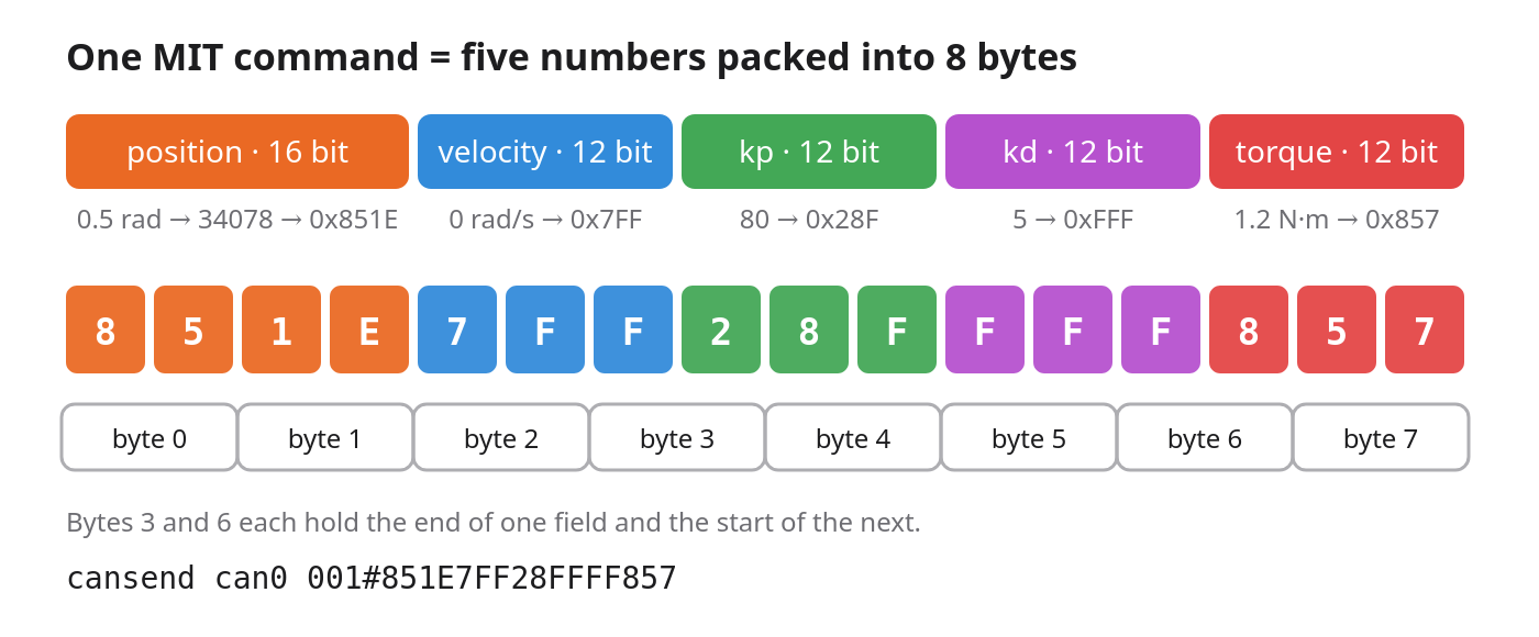
Every other command is a spring. The motors use the "MIT" control protocol. Instead of telling a motor "go to this angle", the computer sending the commands (here, the Orin) tells it "behave like this spring", and the motor's own chip does the work of acting like that spring by computing the equation above, thousands of times a second. Each spring is described by five numbers, squeezed into one 8-byte message.
The five numbers are the target position, the target velocity, the stiffness (kp), the damping (kd), and a feed-forward torque. Reading the equation from left to right: the further the joint is from its target, the harder it is pulled back; the further its velocity drifts from the target, the more it is slowed; and the feed-forward term adds a constant push, for example, to hold the arm up against gravity.
This makes a single command very flexible. With high stiffness, the joint holds firm; with stiffness and damping at zero, it goes limp and can be moved by hand. Position is encoded in 16 bits and each of the other four values in 12 bits, which is how all five fit into 8 bytes.
For example, to send the shoulder to 0.5 rad with a stiffness of 80, a damping of 5, and 1.2 N·m of feed-forward torque:
python -m direct_can.frames mit --motor-id 1 --pos 0.5 --kp 80 --kd 5 --torque 1.2
001#851E7FF28FFFF857
Eight bytes, one motor, one reply. That is the whole language.
The Orin already speaks CAN
Conveniently, the NVIDIA Jetson AGX Orin has two CAN controllers built into the chip, brought out on its 40-pin header. Each controller only needs a transceiver, a small board that turns the controller's logic pins into the CAN-H/CAN-L pair. We used an SN65HVD230 board, about $7 per bus.
Why two buses for two arms, when a single bus can carry many motors and sensors? Every YAM arm ships with the same motor IDs. With two arms on one bus, both would answer the same commands and move in mirror. Renumbering the motors was out of scope for us, so we gave each arm its own bus, which lets us control each one independently.
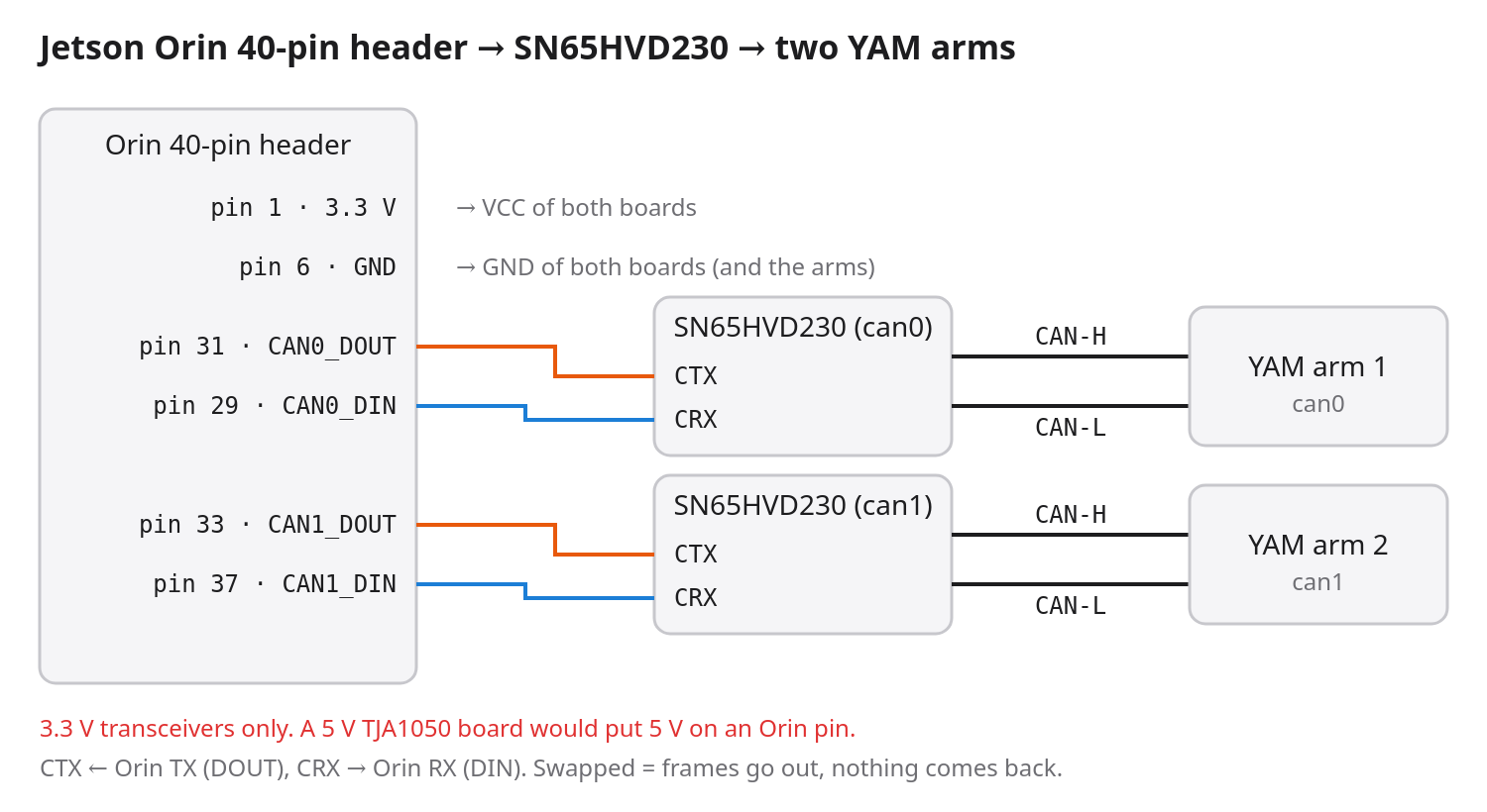
| SN65HVD230 | can0 | can1 |
|---|---|---|
| 3V3 / GND | pin 1 / pin 6 | pin 17 / any GND |
| CTX | pin 31 | pin 33 |
| CRX | pin 29 | pin 37 |
Use only 3.3 V transceiver boards, wire TX to TX (this is not a crossed serial link), and share a ground between the arm and the Orin. A single command then brings the bus up:
sudo direct_can/can_bringup.sh can0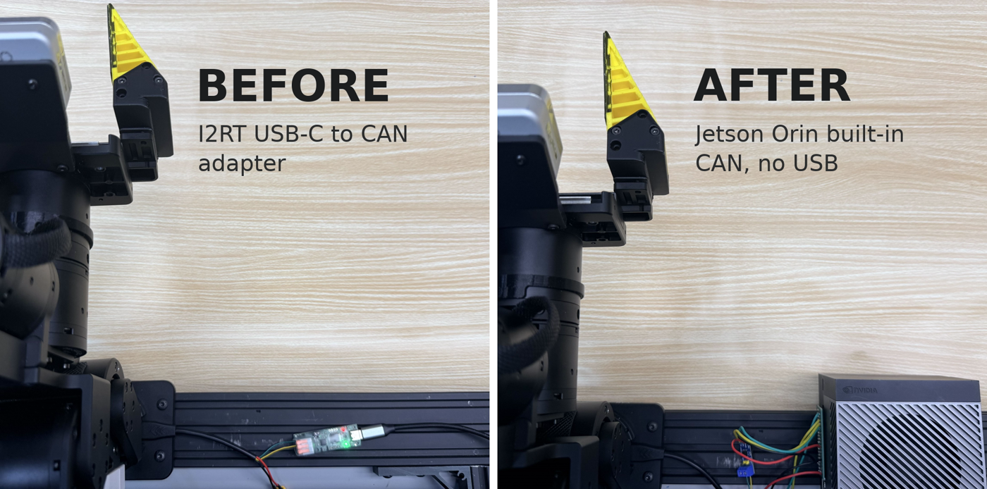
To the computer, the new connection looks exactly like the old one, so I2RT's software runs without a single change. The difference is what is gone: no adapter, no hub, and nothing in the middle that can unplug and replug itself. If something does go wrong, the computer now reports it, instead of the arm quietly losing its connection.
To drive the arm, we move a second, hand-held "leader" arm, and the YAM follows it. I2RT's software converts each movement into the spring commands described above while keeping the arm supporting its own weight as it moves.
Results
A connection is only as good as the test it survives, so we tried to break it. On new cables, we had all seven motors of one arm exchanging messages as fast as the bus allows for 30 seconds, while wiggling the cable at both ends.
Out of more than 81,000 messages over 30 seconds, not a single one went missing, and every motor answered in about a thousandth of a second.
Through the USB hubs, a few messages in every million vanished, and a single lost message is enough to freeze an arm. Now, in live use, the follower arm and its gripper track the leader smoothly. And because the connection no longer drops out from under it, stopping the arm now holds it safely in place instead of letting it fall.
The Bigger Picture: One Box for VLAs
So, is converting from USB to CAN feasible? Yes, and it costs a few dollars and an afternoon of wiring.
The bigger win is what the robot becomes. One Jetson AGX Orin now drives the arms directly over CAN, while also running a GMSL camera setup and the policy itself on-device. Arms, cameras, and model all sit in one box, on one clock, with no USB chain in between. For teams building with vision-language-action (VLA) models, this is a neat, secure, and clean one-stop solution.
Owning the bus also opens the door to new sensors: any CAN node can join can0, and the Orin's header also exposes I²C, SPI, and UART. Custom hardware can now plug straight into the arm's own bus, instead of living on a separate board whose signals have to be stitched together on a PC. That means simpler integration, a wider range of open-source sensors and drivers to choose from, and more room to try new things with VLAs. Open-source projects such as FlexiTac tactile sensors are straightforward to add.
Everything in direct_can/, our fork of I2RT's library, is open source, including every CAN frame and the wiring guide.
We're excited to see what the community builds with it.
Acknowledgments
This project would not have been possible without the support of the team. Thank you to: